Vor Antenna Aircraft - Marker beacon signals are highly directional, which means you have to be almost directly over the transmitting ground station to receive them; therefore, marker beacon antennas need to be on the bottom of the aircraft. There are a few different types of marker antennas;
the more common types look like little canoes about 10 inches long. For some installations, Cessna has used flush antennas that appear to be flat plates under the empennage. It also has used an antenna that consists of a thick wire that protrudes straight down out of the empennage and then makes a turn towards the tail.
Vor Antenna Aircraft

In order to join and track a specific radial using this type of display, the card is rotated until the OBI reads the correct bearing and the needle then indicates whether to fly a heading to the right or left of the selected bearing to approach the required radial
Marker Beacon Antennas
. Hopefully, you'll never have to use an emergency locator transmitter antenna, but in case you do, they are designed to survive an "unscheduled" landing. They are almost always on the upper skin of the empennage and are made of a flexible material.
There are a few exceptions, though; some may be buried in the vertical tail or look like small com antennas. S65-247-38: System consists of two blade antennas with stainless steel leading edges, 24 inch cables, alignment rod and phasing coupler.
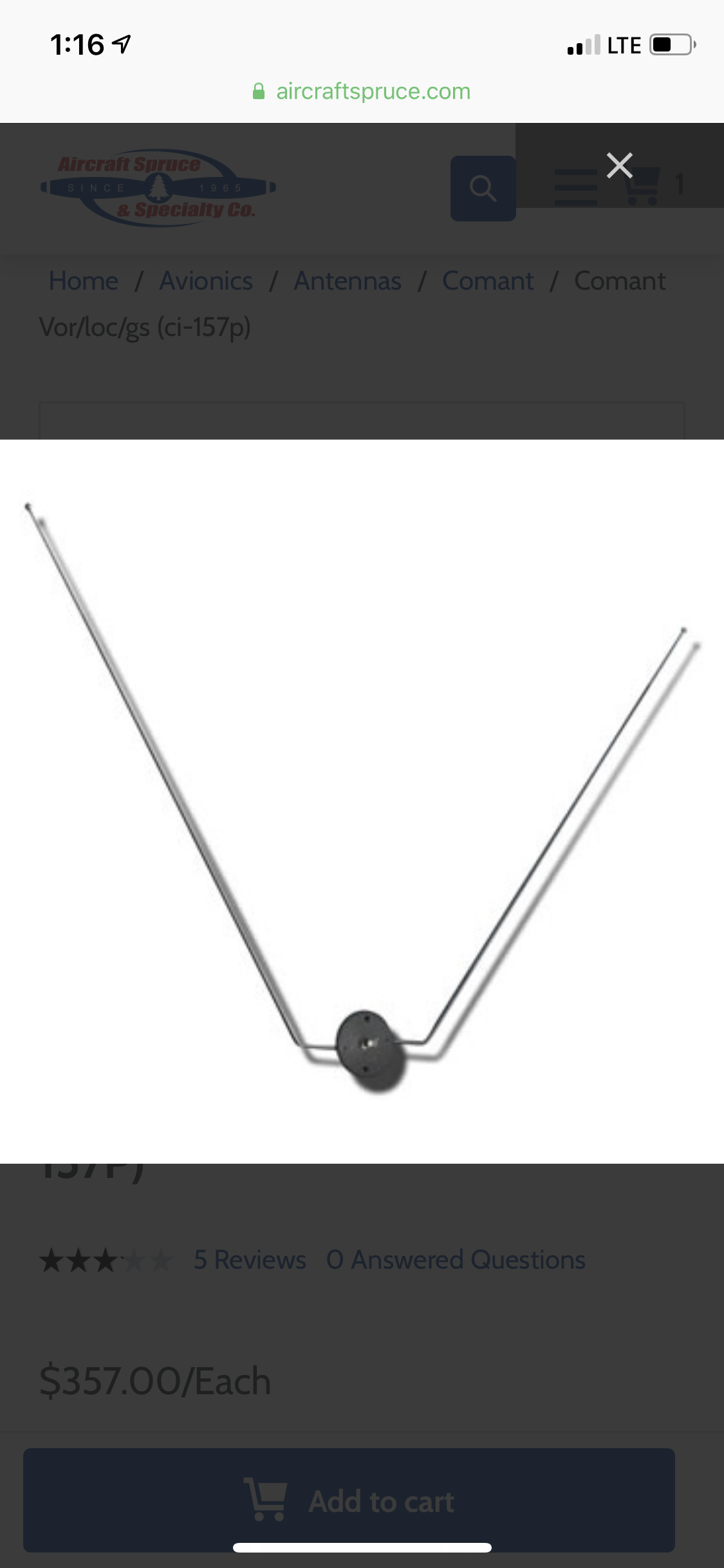
The system is a balanced loop design with omni-directional radiation pattern ensuring maximum signal strength. The coupler included is for the dual VOR installation. Designed for installation on general aviation aircraft as well as business jets and helicopters.
Phasing Coupler/Power Divider SSPD-113-38 is tuned to the VOR antenna blades for dual VOR installations, eliminating the need for additional power dividers. GPS satellites transmit less than five watts of power, so by the time the signal reaches you, it is very, very weak.
Navigation Using Cdi
Because of this, the GPS antenna has a built-in amplifier to boost the signal for the receiver. Additionally, the GPS frequency is so high (in the gigahertz band) that the signals travel in a line-of-sight manner.
This makes receiving the signal susceptible to airframe shadowing, thus mandating that a GPS antenna be mounted at the very top of the fuselage. The omnidirectional (or reference) signal is 30 Hz (frequency modulated) on a subcarrier of 9950 Hz (amplitude modulated) with a deviation of + 480 Hz.
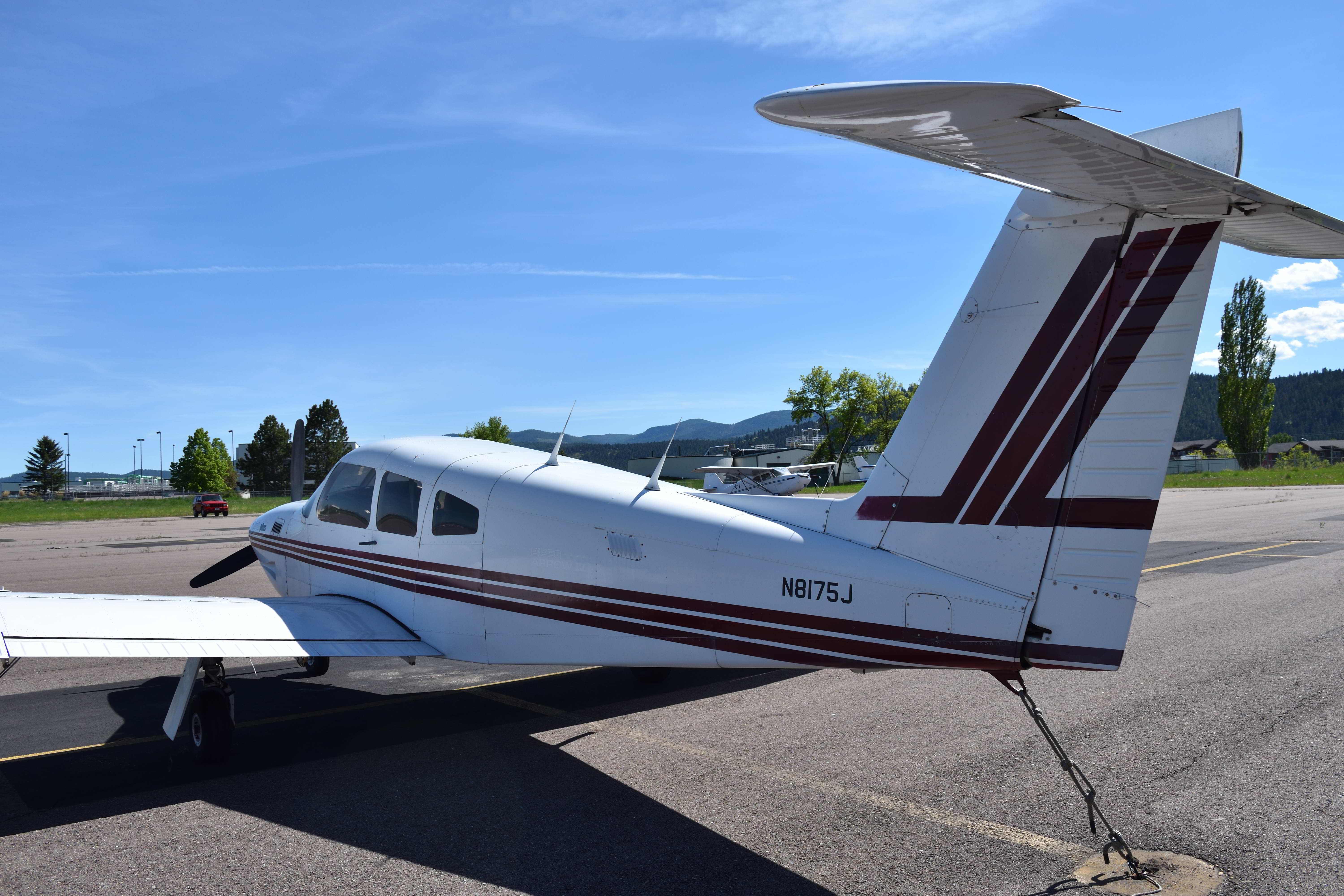
The directional (variable) signal is 30 Hz (Amplitude Modulated) radiated as a cardioid pattern, electronically rotating clockwise at 30 revolutions per second. "V" dipole VOR/ Glide Slope antenna with fixed elements designed specifically for compatibility with the Piper Aircraft mounting.
Integral ferrite balun provides for higher radiation efficiency replacing cumbersome coaxial baluns previously utilized. Radiating elements are not removable. The clockwise angle for the north pole to the radio station is termed as bearing to an station.
Emergency Locator Transmitter Antennas
If the angle is taken from the magnetic north it is termed as Magnetic Bearing and if the angle is taken from true north then it is termed as True Bearing. The OBI is moved around the same display as the direction indicator and always shows the bearing relative to the current heading and when the aircraft turns, the OBI rotates with the direction indicator.
Thus, the direction the aircraft is going relative to the selected bearing is always clear and easy to read. The actual reading presented to the pilot is the bearing to the station rather than from, so if the difference in phase between variable and reference signal is 135° the 'to' bearing would be 135 + 180 = 315º.
RMI has a rotating compass card hence is capable of indicating the heading of the aircraft. It consists of two pointer which can display indication from two different VOR station or one pointer can display indication from VOR station while other indicator can display indication from ADF station which depends on the selector knob position.
The RMI does not indicate TO and FROM indications or FLY LEFT or FLY RIGHT Commands. The RMI provides the pilot with the heading of the aircraft, the bearing to the station and the relative bearing.

Gps Antennas
If we now add 180 to the phase-shifted reference phase we have R + C + 180 which will, on addition, either cancel V, partially or completely, in which case a TO indication will be given, or reinforce V, partially or completely.
, in which case a FROM indication will be given. The omni bearing selector (OBS) knob is used to select the desired course in case of manual VOR flying. The CDI only indicates the selected course to the VOR station and is independent of the heading of the aircraft.
Due to the site errors in the CVOR, the Doppler VOR (DVOR) was developed. It works on the Doppler effect which can be summarized here as: '...the frequency of a wave apparently changes as its source moves closer to, or farther away from an observer'.
VOR navigation aids are identified by unique three-letter codes. The code is modulated onto the carrier wave as a 1020 Hz tone that the crew can listen to as a Morse code signal. Some VOR navigation aids have an automatic voice identification announcement that provides the name of the station;
Navigation Using Hsi Or Ehsi
this alternates with the Morse code signal. There are two most commonly used types are VOR (CVOR) and the Doppler VOR (DVOR). They both use the same design of VHF antenna to generate the carrier, which is known as the Alford loop, It consists of a pair of resonant 90 dipoles arranged in a square and each fed in anti phase from the oscillator.
The only difference being methods to produce the variable and reference 30 Hz modulation. When the aircraft is flying towards the station the aircraft has to fly (heading) in the opposite radial bearing of the radio station as it has to fly to the station.
When the aircraft is flying away from the station it has to fly (heading) in the same direction as the station bearing as it is going away from the station. Bearing TO the station and Bearing FROM the station.
The TO and FROM bearing depends on the heading or the position of the aircraft with respect to the station, whether it is flying towards (TO) the station or away (FROM) from the station. VOT - This is found at certain airfields and broadcasts a fixed omni-directional signal for a 360° test radial.
Uhf Antennas
This is not for navigation use but is used to test an aircraft's equipment accuracy before IFR flight. More than +/-4° indicates that the equipment needs servicing. ILS frequencies are allocated to the odd tenths of each 0.5 MHz increment, e.g.
109.10 MHz, 109.15 MHz, 109.30 MHz, etc. VOR frequencies are allocated to even tenths of each 0.5 MHz increment, e.g. 109.20 MHz, 109.40 MHz, 109.60 MHz, etc. The VOR station works on the lighthouse principle, and assume you're sitting north of the lighthouse and watching the beam go around, you see a bright flash only when the light points directly at you.
At that moment, start counting to see how much time it takes for the beam to flash again. Let's say the beam takes 40 seconds for one rotation, or 360 degrees, now you can convert the number of seconds into where the beam is aimed at any time.
So by the time is 10 seconds from the flash the beam would be pointing east (90º), by time 20 seconds from the flash the beam would be pointing south (180º), and by counting 30 seconds from the flash, the beam will be
To And From Indications
pointing west (270º) and at time 40 sec from the flash the beam will be pointing North again (0º or 360º). Selected course (track) is displayed by the magenta course needle, the tip pointing to the selected course (150).
The course selectors are usually on either side of the autoflight main control panel (one for the Captain and one for the First Officer). Course deviation is shown by the traditional deviation bar moving across a two dot left and two dot right scale.
Toll Free: 877-477-7823 Customer Service: 800-861-3192 Fax: 800-329-3020 CDI indicates the selected course which can be selected using the Omni Bearing Selected (OBS) and has a fixed card i.e. the card does not rotate with the heading of the aircraft.
The indication will always point to the selected radial and is independent of the aircraft heading. Modern antennas come in many different shapes and sizes. Each antenna is formed by its function. Often, a well-equipped airplane will have an antenna farm on the belly, and it can be confusing to try to figure out what each antenna does.
Aircraft Heading
But taken one by one, those antennas are easier to understand. The frequencies at which they operate and their directional qualities usually determine their shape and placement. Course selection is displayed by the magenta course needle, the tip pointing to the selected course (150).
Course deviation is shown by the traditional deviation bar moving across a two dot left and two dot right scale. UHF antennas are commonly used for transponders and distance measuring equipment (DME), and they are always found on the bottom of the aircraft.
They are about four inches long, and the same antenna can be used for both systems because the transponder frequency is in the middle of the DME frequency band. Two types are commonly used: spike and blade antennas.
The spike should only be used for transponders because the antenna length is tuned to one frequency—the transponder frequency. The blade antenna is also called a broadband antenna because it is tuned for a range of DME frequencies.
Performance Consideration
A spike would not work very well for a DME; the blade antennas are preferred because the radiation pattern is better. The TO indication are displayed when an aircraft is flying towards the station and the FROM indications are displayed when flying away from the station.

The deviation pointer will show zero deviation when the aircraft is flying on the desired radial. Hence to calculate the position of the station with respect to the north the phase difference is calculated. The two signals are in phase along magnetic North, they are 90º out of phase in the East, they are 180º out of phase in the South and 270º out of phase in the West.
The received radio frequency signal is passed through an amplitude modulation and frequency modulation filter to separate the various signals and fed to the phase detector. A comparison of the phase angles of the variable and reference 30 Hz signals produces the VOR radial signal.
Locations of conventional VOR (CVOR) ground stations have to be carefully planned to take into account local terrain and obstacles. Mountains and trees can cause multipath reflections, resulting in distortion (known as siting errors) of the radiated signal.
Nav Antennas
These errors can be overcome with an enhanced second-generation system known as Doppler VOR (DVOR). The clockwise angle from the north pole to the nose of the aircraft is termed as heading of an aircraft. If the direction is taken from magnetic north it is termed as Magnetic Heading, If the direction is taken from true north it is termed as True Heading.
Had to purchase this bc mine broke. When they manufactured it they drilled a hole that wasn't centered for the roll pin that goes to the antenna wire itself. Vibration eventually broke it. I called the manufacturer directly and left several messages and no reply.
I guess when you sell $357.00 cost hangers, you don't have to answer to anyone! Please note, Aircraft Spruce's personnel are not certified aircraft mechanics and can only provide general support and ideas, which should not be relied upon or implemented in lieu of consulting an A&P or other qualified technician.
Aircraft Spruce assumes no responsibility or liability for any issue or problem which may arise from any repair, modification or other work done from this knowledge base. Any product eligibility information provided here is based on general application guides and we recommend always referring to your specific aircraft parts manual, the parts manufacturer or consulting with a qualified mechanic.
Communication Antennas
vor antenna installation, vor ils antenna, aircraft antenna locations, aircraft vor system, vor antenna balun, aircraft antennas types, vor antenna design, vor and localizer antenna